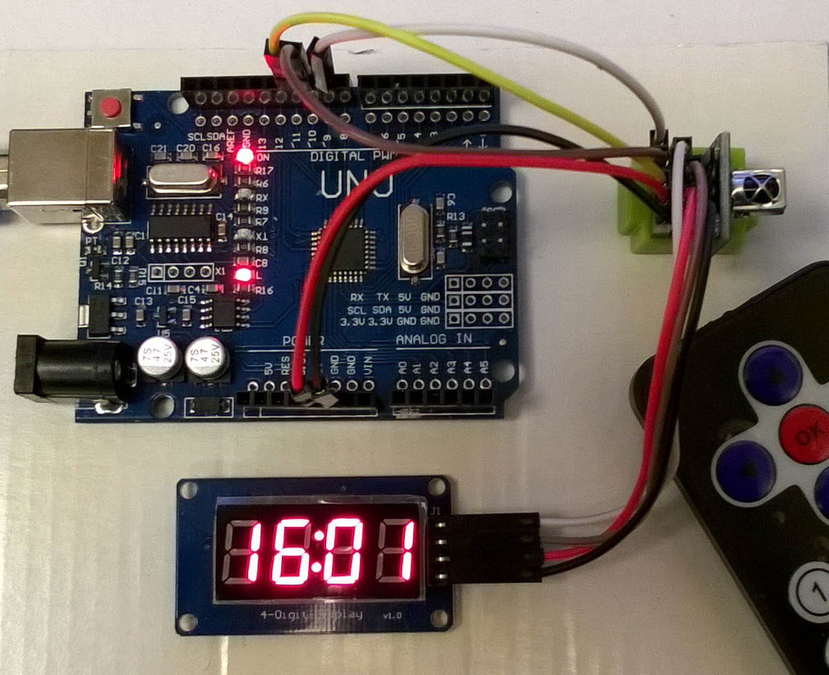


The I 2C bus relies on pull-up resistors to pull the signals high, devices on the bus only drive it low. In this case the control signals appeared to have large capacitive loading on them, at least the RobotDyn module did. It can be a fast way to verify that things are doing what you expect, and it can save a lot of time troubleshooting when things aren’t working. Whenever I’m developing stuff I like to hook up an oscilloscope to the hardware signals to see what’s happening. The next problem I had was not the TM1637 itself but one of the modules I’d bought. If you’re bit-banging the interface it’s easy enough to reverse the bit order of data being shifted out, but if you want to use the PIC’s MSSP module then it’s going to send it MSB first, so you need to reverse the byte before loading the SSPxSR buffer register.įor example the TM1637 Data command setting for ‘ Write data to display register with automatic address adding‘ is 0b01000000 (0x40) so you need to load the SSPxSR register with 0b00000010 (0x20) so it arrives at the TM1637 LSB first. What it doesn’t make clear is that it expects data to be sent LSB first, and this caught me out for a while. Well that’s not too much of a problem, it does mean you can’t have any other devices on the bus but that’s not a show stopper. At first glance it looks like an I 2C interface, however the datasheet points out that “ it is not equal to I 2C bus protocol totally because there is no slave address“. The translated data sheet for the device describes communication with the TM1637 by means of a two-wire bus interface. The first thing to catch me out was the I 2C interface that isn’t. Since I had some ‘fun and games’ getting them working, I thought I’d share my findings here. You can find these on eBay, Amazon and all the usual resellers of maker hardware. I recently got hold of some 7-segment LED modules that use the TM1637 LED drive controller IC.


 0 kommentar(er)
